

Main Blocks in the Architecture
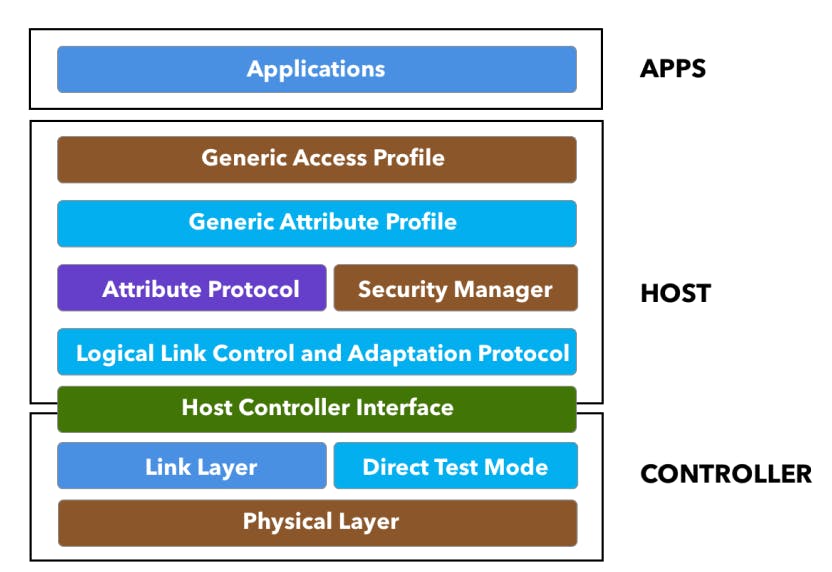
The following figure shows the different layers within the architecture of BLE. The three main blocks in the architecture of a BLE device are:
Application
Host
Controller
Application
The Application layer is use-case dependent and refers to the implementation on top of the Generic Access Profile and Generic Attribute Profile — it is how your application handles data received from and sent to other devices and the logic behind it.
This portion is the code that you would write for your specific BLE application and is generally not part of the BLE stack for the platform that you develop.
Host
The Host contains the following layers:
Generic Access Profile (GAP)
Generic Attribute Profile (GATT)
Attribute Protocol (ATT)
Security Manager (SM)
Logical Link Control and Adaptation Protocol (L2CAP)
Host Controller Interface (HCI) — Host side
Controller
The Controller contains the following layers:
Physical Layer (PHY)
Link Layer
Direct Test Mode
Host Controller Interface (HCI) — Controller side
Lower-level Layers
Physical Layer (PHY)
The physical layer (PHY) refers to the radio hardware used for communication and for modulating/de-modulating the data. BLE operates in the ISM band (2.4 GHz spectrum), which is segmented into 40 RF channels, each separated by 2 MHz (center-to-center), as shown in the following figure:
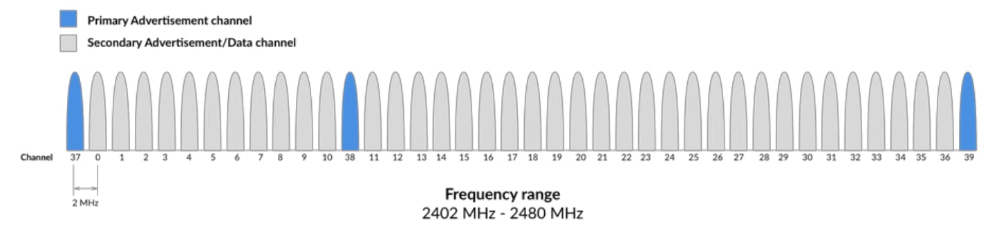
Three of these channels are called the Primary Advertising Channels, while the remaining 37 channels are used for Secondary Advertisements and for Data Transfer during a connection.
Advertising always starts with advertisement packets being sent on the three Primary Advertising Channels (or a subset of these channels). This allows the devices that are scanning for advertisers to find them and read their advertisement data.
The scanner can then initiate a connection if the advertiser allows it. It can also request what is called a scan request, and if the advertiser supports this scan request functionality, it will respond with a scan response.
Scan Request and Scan Response allow the advertiser to send additional advertisement data to devices that are interested in receiving this data.
Here are some other important technical details about the Physical Radio:
It uses Frequency Hopping Spread Spectrum (FHSS), which allows the two communicating devices to switch to randomly (agreed-on) selected frequencies for exchanging data. This greatly improves reliability and allows the devices to avoid frequency channels that may be congested and used by other devices in the surrounding environment.
The transmit power levels are:
Maximum:
100mW (+20 dBm) for version >= 5
10mW (+10 dBm) for version <= 4.2
Minimum: 0.01mW (-20 dBm)
In older versions of Bluetooth (4.0, 4.1, and 4.2), the data rate was fixed at 1 Mbps. The physical layer radio (PHY) in this case is referred to as the 1M PHY and is mandatory in all versions including Bluetooth 5. With Bluetooth 5, however, two new optional PHYs were introduced:
2Mbps PHY, used to achieve twice the speed of earlier versions of Bluetooth.
Coded PHY, used for longer-range communication.
Link Layer (LL)
The Link Layer is the layer that interfaces with the physical layer (radio) and provides the higher-level layers an abstraction and a way to interact with the radio (through an intermediary level called the HCI). It is responsible for:
Managing the state of the radio as well as the timing requirements necessary for satisfying the BLE specification.
Managing hardware-accelerated operations such as CRC, random number generation, and encryption.
The three main states in which a BLE device operates are:
Advertising state
Scanning state
Connected state
When a device advertises, it allows other devices that are scanning to find the device and possibly connect to it. If the advertising device allows connections and a scanning device finds it and decides to connect to it, they each enter into the connected state.
The link layer manages the different states of the radio, shown in the following figure:
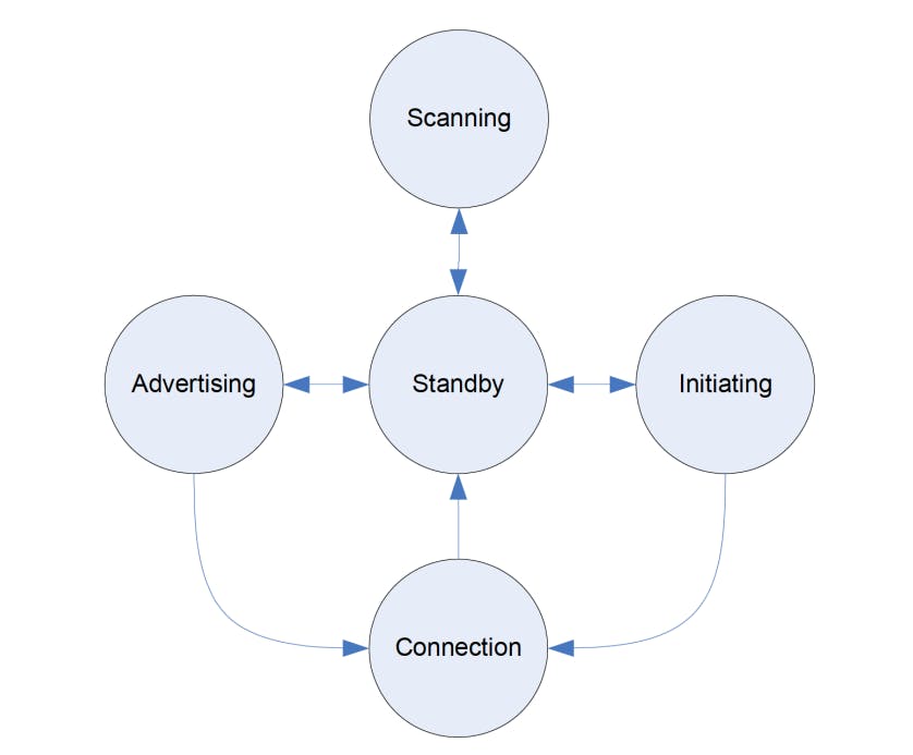
Standby: the default state in which the radio does not transmit or receive any data.
Advertising: the state in which the device sends out advertising packets for other devices to discover and read.
Scanning: the state in which the device scans for devices that are advertising.
Initiating: the state in which a scanning device decides to establish a connection with a device that is advertising.
Connected: the state in which a device has an established link with another device and regularly exchanges data with this other device.
In this connected state, the device that initiates the connection is called the master, and the device that was advertising is now called the slave.
Bluetooth Address
Bluetooth devices are identified by a 48-bit address, similar to a MAC address. There are two main types of addresses:
Public Addresses
Random Addresses
Public Addresses
This is a fixed address that does not change and is factory-programmed. It must be registered with the IEEE (similar to a Wi-Fi or Ethernet device MAC address).
Random Address
Since manufacturers have a choice on what type of address to use (Random vs. Public), Random addresses are more popular since they do not require registration with the IEEE. A random address is programmed on the device or generated at runtime. It can be one of two sub-types:
Static Address
Used as a replacement for Public Address.
Can be generated at boot-up or stay the same for a lifetime.
Cannot change until a power cycle.
Private Address
This one is also split up into two additional sub-types:Non-resolvable Private Address
Random, temporary for a certain time.
Not commonly used.
Resolvable Private Address
Used for privacy.
Generated using Identity Resolving Key (IRK) and a random number.
Changes periodically (even during the lifetime of the connection).
Used to avoid being tracked by unknown scanners.
Trusted devices (or Bonded) can resolve it using the previously stored IRK.
Direct Test Mode (DTM)
Direct Test Mode (DTM) is only needed for performing RF tests and is used during manufacturing and for certification tests.
Host Controller Interface (HCI)
The HCI layer is a standard protocol defined by the Bluetooth specification that allows the Host layer to communicate with the Controller layer. These layers could exist in separate chipsets, or they could exist in the same chipset. In this sense, it also allows interoperability between chipsets, so a device developer can choose two Bluetooth-certified devices, a controller and a host, and be 100% confident that they are compatible with each other in terms of communication between the host and controller layers.
In the case where the host and controller are in separate chipsets, the HCI layer will be implemented over a physical communication interface. The three officially supported hardware interfaces by the spec are UART, USB, and SDIO (Secure Digital Input Output). In the case where the two layers (host and controller) live on the same chipset, the HCI layer will be a logical interface instead.
The job of the HCI layer is to relay commands from the host down to the controller and send events back up from the controller to the host.
Logical Link Control and Adaptation Protocol (L2CAP)
The Logical Link Control and Adaptation Protocol (L2CAP) layer acts as a protocol-multiplexing layer. It is borrowed from the Bluetooth Classic standard, and performs the following tasks in the case of BLE:
Takes multiple protocols from the upper layers and places them in standard BLE packets that are passed down to the lower layers beneath it.
Handles fragmentation and recombination.
It takes the larger packets from the upper layers and splits them into chunks that fit into the maximum BLE payload size supported for transmission.
On the receiver side, it takes multiple packets and combines them into one packet that can be handled by the upper layers.
For BLE, the L2CAP layer handles two main protocols:
The Attribute Protocol (ATT)
The Security Manager Protocol (SMP)
Upper-level Layers
The Upper-level layers of BLE Architecture include:
The Attribute Protocol (ATT)
Security Manager (SM)
Generic Attribute Profile (GATT)
Generic Access Profile (GAP)