


The Register File
Since numbers must first be fetched from storage before they can be added, we want our data storage space to be as fast as possible so that the operation can be carried out quickly. Since the ALU is the part of the processor that does the actual addition, we’d like to place the data storage as close as possible to the ALU so it can read the operands almost instantaneously. However, practical considerations, such as a CPU’s limited surface area, constrain the size of the storage area that we can stick next to the ALU. This means that in real life, most computers have a relatively small number of very fast data storage locations attached to the ALU. These storage locations are called registers, and the first x86 computers only had eight of them to work with. These registers, which are arrayed in a storage structure called a register file, store only a small subset of the data that the code stream needs.
Building on our previous, three-step description of what goes on when a computer’s ALU is commanded to add two numbers, we can modify it as follows. To execute an add instruction, the ALU must perform these steps:
Obtain the two numbers to be added (the input operands) from two source registers.
Add the numbers.
Place the results back in a destination register.
For a concrete example, let’s look at addition on a simple computer with only four registers, named A, B, C, and D. Suppose each of these registers contains a number, and we want to add the contents of two registers together and overwrite the contents of a third register with the resulting sum, as in the following operation:
Code:
A + B = C

Comment:
Add the contents of registers A and B, and place the result in C, overwriting
whatever was there.
Upon receiving an instruction commanding it to perform this addition operation, the ALU in our simple computer would carry out the following three familiar steps:
Read the contents of registers A and B.
Add the contents of A and B.
Write the result to register C.
This three-step sequence is quite simple, but it’s at the very core of how a microprocessor really works.
RAM: When Registers Alone Won’t Cut It
Obviously, four (or even eight) registers aren’t enough space. In order to make a viable computer that does useful work, you need to be able to store very large data sets.
This is where the computer’s main memory comes in. Main memory, which in modern computers is always some type of random access memory (RAM), stores the data set on which the computer operates, and only a small portion of that data set at a time is moved to the registers for easy access from the ALU.
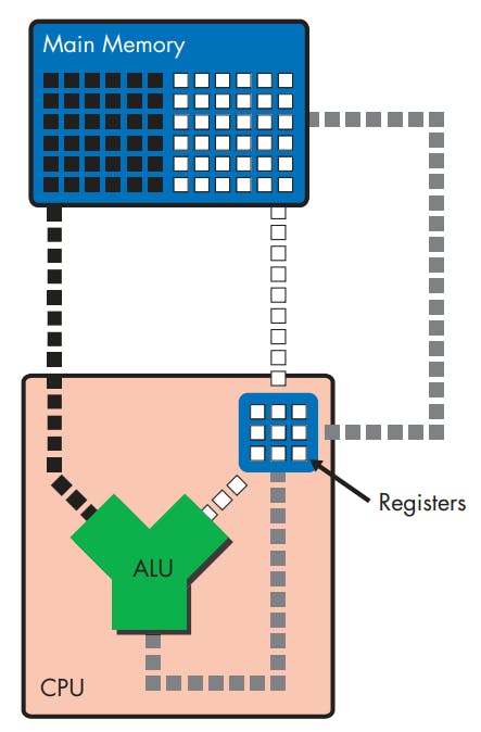
The above figure gives only the slightest indication of it, but main memory is situated quite a bit farther away from the ALU than are the registers. In fact, the ALU and the registers are internal parts of the microprocessor, but main memory is a completely separate component of the computer system that is connected to the processor via the memory bus.
Transferring data between main memory and the registers via the memory bus takes a significant amount of time. Thus, if there were no registers and the ALU had to read data directly from main memory for each calculation, computers would run very slowly. However, because the registers enable the computer to store data near the ALU, where it can be accessed nearly instantaneously, the computer’s computational speed is decoupled somewhat from the speed of main memory.
The File-Clerk Model Revisited and Expanded
To return to our file-clerk metaphor, we can think of main memory as a document storage room located on another floor and the registers as a small, personal filing cabinet where the file clerk places the papers on which he’s currently working. The clerk doesn’t really know anything about the document storage room—what it is or where it is located—because his desk and his personal filing cabinet are all he concerns himself with.
For documents that are in the storage room, there’s another office worker, the office secretary, whose job it is to locate files in the storage room and retrieve them for the clerk. This secretary represents a few different units within the processor.
When the boss wants the clerk to work on a file that’s not in the clerk’s personal filing cabinet, the secretary must first be ordered, via a message from the boss, to retrieve the file from the storage room and place it in the clerk’s cabinet so that the clerk can access it when he gets the order to begin working on it.
An Example: Adding Two Numbers
To translate this office example into computing terms, let’s look at how the computer uses main memory, the register file, and the ALU to add two numbers.
To add two numbers stored in main memory, the computer must perform these steps:
Load the two operands from main memory into the two source registers.
Add the contents of the source registers and place the results in the destination register, using the ALU. To do so, the ALU must perform these steps:
Read the contents of registers A and B into the ALU’s input ports.
Add the contents of A and B in the ALU.
Write the result to register C via the ALU’s output port.
Store the contents of the destination register in main memory.
Since "the in steps" of step 2 take a trivial amount of time to complete, relative to steps 1 and 3, we can ignore them. Hence our addition looks like this:
Load the two operands from main memory into the two source registers.
Add the contents of the source registers, and place the results in the destination register, using the ALU.
Store the contents of the destination register in main memory.
The existence of main memory means that the user (the boss in our filing-clerk analogy) must manage the flow of information between main memory and the CPU’s registers. This means that the user must issue instructions to more than just the processor’s ALU; he or she must also issue instructions to the parts of the CPU that handle memory traffic. Thus, the preceding three steps are representative of the kinds of instructions you find when you take a close look at the code stream.