For two BLE devices to connect to each other, the following steps need to occur:
The peripheral needs to start advertising and send out connectable advertisement packets.
The central needs to be scanning for advertisements while the peripheral is advertising.
If the central happens to be listening on an advertising channel that the peripheral is advertising on, then the central device discovers the peripheral. It is then able to read the advertisement packet and all the necessary information to establish a connection.
The central then sends a CONNECT_IND packet (also known as a Connection Request packet).
The peripheral always listens for a short interval on the same advertising channel after it sends out the advertising packet. This allows it to receive the connection request packet from the central device which triggers the forming of the connection between the two devices.
After this occurs, the connection is considered created, but not yet established. A connection is considered established once the device receives a packet from its peer device. After a connection is established, the central becomes known as the master, and the peripheral becomes known as the slave. The master is responsible for managing the connection, controlling the connection parameters, and the timing of the different events within a connection.
Connection Events
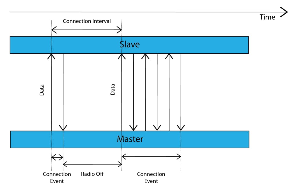
During what's called a connection event, the master and slave alternate sending data packets to each other until neither side has more data left to send. Here are a few aspects of connections that are very important to know:
A Connection Event occurs periodically and continuously until the connection is closed or lost.
A Connection Event contains at least one packet sent by the master.
The slave always sends a packet back if it receives a packet from the master.
If the master does not receive a packet back from the slave, the master will close the connection Event — it resumes sending packets at the next connection Event.
The connection Event can be closed by either side.
The starting points of consecutive Connection Events are spaced by a period called the Connection Interval.

Connection Parameters
The parameters that define connections are:
Connection interval
The Connection Interval value ranges between 7.5 milliseconds - 4.0 seconds in increments of 1.25 milliseconds.
It is set by the central device in the connection request packet. The central may take into account the Peripheral Preferred Connection Parameters (PPCP), which is a way for the peripheral to inform the central of a set of parameters that it prefers. In the end, though, it is up to the central whether to respect these values or ignore them.Slave Latency
The slave latency parameter allows the peripheral to skip a number of consecutive connection events and not listen to the central at these connection events without compromising the connection. This allows the peripheral to sleep for longer periods of time, potentially reducing power consumption. The slave latency value defines the number of connection events it can safely skip.Supervision Timeout
The supervision timeout is used to detect a loss in connection. It is defined as the maximum time between two received data packets before the Connection is considered lost. Its value ranges between 100 milliseconds - 32 seconds in increments of 10 milliseconds. Another condition for this timeout value is:
$$𝑆𝑢𝑝𝑒𝑟𝑣𝑖𝑠𝑖𝑜𝑛𝑇𝑖𝑚𝑒𝑜𝑢𝑡>(1 + 𝑐𝑜𝑛𝑛𝑆𝑙𝑎𝑣𝑒𝐿𝑎𝑡𝑒𝑛𝑐𝑦) * 𝑐𝑜𝑛𝑛𝐼𝑛𝑡𝑒𝑟𝑣𝑎𝑙 * 2$$
- The one exception — where the supervision timeout does not apply — is after a connection is created, but not yet established. In this case, the master will consider the connection to be lost if it does not receive the first packet from the slave within:
$$6 * 𝑐𝑜𝑛𝑛𝐼𝑛𝑡𝑒𝑟𝑣𝑎𝑙$$
Data Length Extension (DLE)
This is a setting that can be enabled or disabled. It allows the packet size to hold a larger amount of payload (up to 251 bytes vs. 27 when disabled). This feature was introduced in version 4.2 of the Bluetooth specification.Maximum Transmission Unit (MTU)
MTU stands for Maximum Transmission Unit and is used in computer networking to define the maximum size of a Protocol Data Unit (PDU) that can be sent by a specific protocol. The Attribute MTU (ATT_MTU) is the largest size of an ATT payload that can be sent between a client and a server.The effective ATT_MTU is determined by the minimum value of the maximum ATT_MTU values that the master and slave support. For example, if a master supports an ATT_MTU of 100 bytes and the slave responds that it supports an ATT_MTU of 150 bytes, then the master will decide that the ATT_MTU to be used for the connection from thereon is 100 bytes.
Note: To achieve maximum throughput, make sure you enable DLE*. This reduces the packet overhead and any unnecessary header data that gets transmitted with smaller packets.*
Channel Hopping
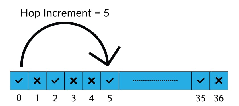
There are 37 RF channels utilized for transmitting data packets during a connection. However, not all 37 channels are necessarily used during a connection. The used channels are defined by the channel map, which is included in the connection request packet sent by the central to the peripheral to initiate a connection. For each connection event, the data packets will be sent on a different channel within the channel map.
The sequence of channels used for each of the connection events is determined by the channel map as well as another value called the hop increment. The hop increment is also included in the connection request packet. The combination of the channel map and hop increment determines which channel gets used at each connection interval.

White List & Device Filtering
BLE supports device filtering for procedures related to:
The Advertising State
The Scanning State
The Initiating State (for establishing connections)
A white list is a list of addresses and address types of specific devices. It is used for determining which peer devices a particular device is interested in. An entry for an anonymous device address type allows matching all advertisements sent with no address.
Device Filtering gets processed at the link layer in the controller (the lower layer of the Bluetooth stack), which saves time and overhead from being performed at the host (the upper layer of the stack). However, the host is responsible for configuring the white list.
Here is a list of the different white list filter policies that apply to each of these states:
Advertising State Filter Policy (Peripheral Side)
This filter policy defines how the advertiser processes both scan and connection requests. The different configurations include:Process scan and connection requests only from devices in the white list.
Process scan and connection requests from all devices (white list not used).
Process scan requests only from devices in the white list while processing connection requests from all devices.
Process connection requests only from devices in the white list while processing scan requests from all devices.
Scanning State Filter Policy (Central Side)
This filter policy defines how the scanner processes advertising packets. The different configurations include:Process advertising packets from all devices (white list not used).
Process advertising packets only from devices in the white list.
Initiating State Filter policy (Central Side)
This filter policy defines how a connection initiator processes advertising packets. The different configurations include:Process and initiate a connection to all devices listed in the white list.
Process and initiate a connection only to a device specified by the host.
Notice that itʼs not an option to process and connect to a connectable advertising device that's not in the white list.